How to Select a Robot Cell for Post-Machining Secondary Operations: Deburring, Edge Grinding and Polishing

Why the secondary operation becomes the bottleneck
Most machining shops do not lose hours in the cut. They lose them after the cut.
Once a part comes off the CNC, it still has to be deburred, have its edges broken or blended, and — depending on the finish specification — be polished. In a large share of metalworking plants these steps are still manual. They are also the steps that are hardest to schedule, hardest to staff consistently, and hardest to hold to a tolerance, because the result depends on hand pressure, tool wear and operator attention rather than on a programmed path.
The result is a familiar pattern: the machining centre runs to a stable cycle, and the finishing bench behind it does not. Work-in-progress accumulates, delivery dates slip, and quality varies between shifts.
This guide is written for engineers and sourcing managers who have already decided that the secondary operation is the problem, and who now need to select a robot cell rather than a robot.
What actually determines cell performance
A deburring, grinding or polishing cell is a system, not a machine. Five variables decide whether it works:
- Part geometry and material — size, weight, edge accessibility, burr type, hardness.
- Robot payload and reach — driven by the part plus the tooling, not by the part alone.
- Process force and compliance — whether the tool follows the surface or the surface follows the tool.
- Abrasive and tooling strategy — belt, disc, brush, spindle, or a combination, and how it is changed.
- Part presentation and fixturing — robot-held part vs. robot-held tool, and how the part is loaded.
Get any of these wrong and the cell will run, but it will not hold the finish you promised.
Matching robot payload and reach to your part
Payload is the single most common specification error in finishing cells. The robot does not carry the part — it carries the part, the gripper, the fixture adaptor, and any dressing or sensing hardware. A part that weighs 8 kg can easily present a 14 kg payload requirement once tooling is included.
Reach matters just as much, but for a different reason. In finishing, reach is not only about getting to the part; it is about getting to the part at the correct tool angle. A robot operating near the edge of its working envelope cannot maintain the wrist orientation that keeps the abrasive in full contact. The practical rule is to size the robot so the finishing path sits comfortably inside the envelope, not at its limit.
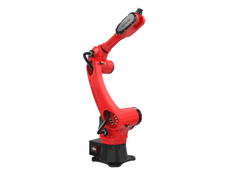
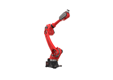
Two six-axis models commonly used as the platform for this class of cell illustrate the trade-off:
| Specification | BRTIRUS1510A | BRTIRUS1820A |
|---|---|---|
| Payload | 10 kg | 20 kg |
| Arm reach | 1587 mm | 1895 mm |
| Repeatability | ±0.05 mm | ±0.05 mm |
| Robot weight | 152 kg | approx. 230 kg |
| Power capacity | 5.06 kVA | 5.87 kVA |
| Axes | 6 | 6 |
| CE conformity | Yes | Yes |
| Explosion-proof variant | No | No |
Specifications per the BORUNTE selection catalogue.
How to read this table. The BRTIRUS1510A suits smaller covers, brackets, housings and similar parts where the total moving mass — part plus gripper — stays within 10 kg and the finishing path fits inside a 1587 mm reach. The BRTIRUS1820A doubles the payload and adds roughly 300 mm of reach, which is what you need when the part is large enough that it must be presented on a positioner, or when the tooling itself is heavy.
Note that repeatability is identical on both models. If your finish specification depends on path accuracy rather than on force, the smaller robot is not a compromise — it is the more economical correct answer.
One boundary worth stating early: neither model carries an explosion-proof rating. If your process generates combustible dust or operates in a hazardous atmosphere, that requirement has to be resolved before model selection, not after.
Force control: the specification that decides whether the cell works
Rigid position control is the wrong control strategy for most finishing work. Castings vary, forgings vary, and even machined parts vary within their own tolerance band. A robot following a fixed path into a varying surface either cuts too little or cuts too much.
Compliant force control changes the relationship: the tool is held against the surface with a controlled force, and the robot path adapts to the actual surface position. This is what makes consistent edge blending possible on parts that are not perfectly repeatable.
When specifying force control for a finishing cell, four parameters need to be defined with the integrator:
- Target contact force and the tolerance band around it
- Force direction — normal to the surface, or with a tangential component for edge breaking
- Compliance behaviour on approach and retract, so the tool does not impact the edge
- Response to force deviation — whether the cell adjusts feed, retracts, or signals a fault
Force control is also what allows one cell to run several part numbers without mechanical re-setup, because the compliance absorbs the geometric differences between them.
Abrasive and tooling strategy
Tooling selection follows from the finish specification, and it is usually a sequence rather than a single operation:
- Deburring — carbide burrs, countersinks or ceramic fibre brushes, depending on burr size and whether the burr is on a face or a hole edge.
- Edge grinding / blending — coated abrasive belts or flap discs, selected by grit and by the material removal rate the cycle can tolerate.
- Polishing — progressively finer abrasive or non-woven media, often with a compliant backing so the tool follows the surface contour.
Two practical points that affect cell design more than tool choice itself:
Tool wear is a process variable. Abrasive media change dimension as they wear. A cell that does not compensate for wear — through force control, through periodic re-teaching, or through automatic tool compensation — will drift out of specification over a shift.
Tool change determines uptime. If the cell runs multiple operations, decide early whether tool change is manual, automatic via a tool changer, or handled by a second spindle. This decision affects robot payload, cell footprint and cycle time simultaneously.
Robot-held part or robot-held tool?
The configuration choice is driven by part size and by how the part arrives at the cell.
| Configuration | Best suited to | Main considerations |
|---|---|---|
| Robot holds the part, tool is fixed | Small to medium parts, high volume, simple geometry | Payload must cover part + gripper; part handling integrates naturally with the upstream process |
| Robot holds the tool, part is fixtured | Large or heavy parts, complex geometry, multiple faces | Robot payload covers tool and force-control unit; part fixturing must be rigid and repeatable |
| Robot holds part on a positioner | Parts needing access to several faces | Adds an axis and a control integration; increases reach requirement |
For a cell fed directly from a CNC, the robot-held-part configuration usually integrates more cleanly, because the same handling logic can serve both the machine tending and the finishing operation.
Building the business case when the CNC is already running
The most common objection to a finishing cell is that the machining centre is already installed and running, so the capital has already been spent. That framing treats the finishing cell as an addition to an existing process, when in fact it is the completion of one.
A more useful way to build the case is to quantify what the manual finishing operation currently costs:
- Labour hours per part, including the rework and touch-up that manual finishing generates
- Scrap and rework rate attributable to inconsistent edge quality
- WIP and lead time held between machining and finishing
- Quality escapes traced back to burrs or edge condition
- Recruitment and training burden for a task that is difficult to staff and difficult to retain
Against those, the cell contributes stability rather than raw speed. The value is that the finishing result becomes repeatable — the same edge on the first part of the shift and the last, on the day shift and the night shift. For shops supplying regulated or safety-critical customers, that consistency is often the deciding factor on its own.
A second consideration is flexibility. A cell built around force control and a defined tool set can be re-tasked across part families without mechanical re-setup, which means the finishing operation stops being the constraint on which new work the shop can accept.
Where integration experience matters
Selecting a robot model is a small part of the problem. The larger part is making the cell work in a real production environment — matching the force-control strategy to the actual part variation, choosing abrasive media that survive the cycle, integrating the cell with the existing CNC handling, and setting up the safety and control architecture around it.
YGT Robot works as a system integrator and application solution provider for industrial robot cells, covering solution design, integration, on-site service and project delivery. In finishing applications, the work typically starts with the part drawing and the finish specification rather than with a robot model, because the required force strategy and tooling sequence determine which platform is appropriate.
The robot platforms used in these cells are supplied by BORUNTE; YGT Robot's role is the cell architecture, the process integration and the delivery.
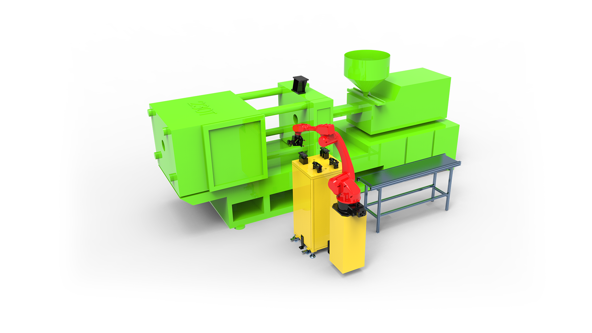
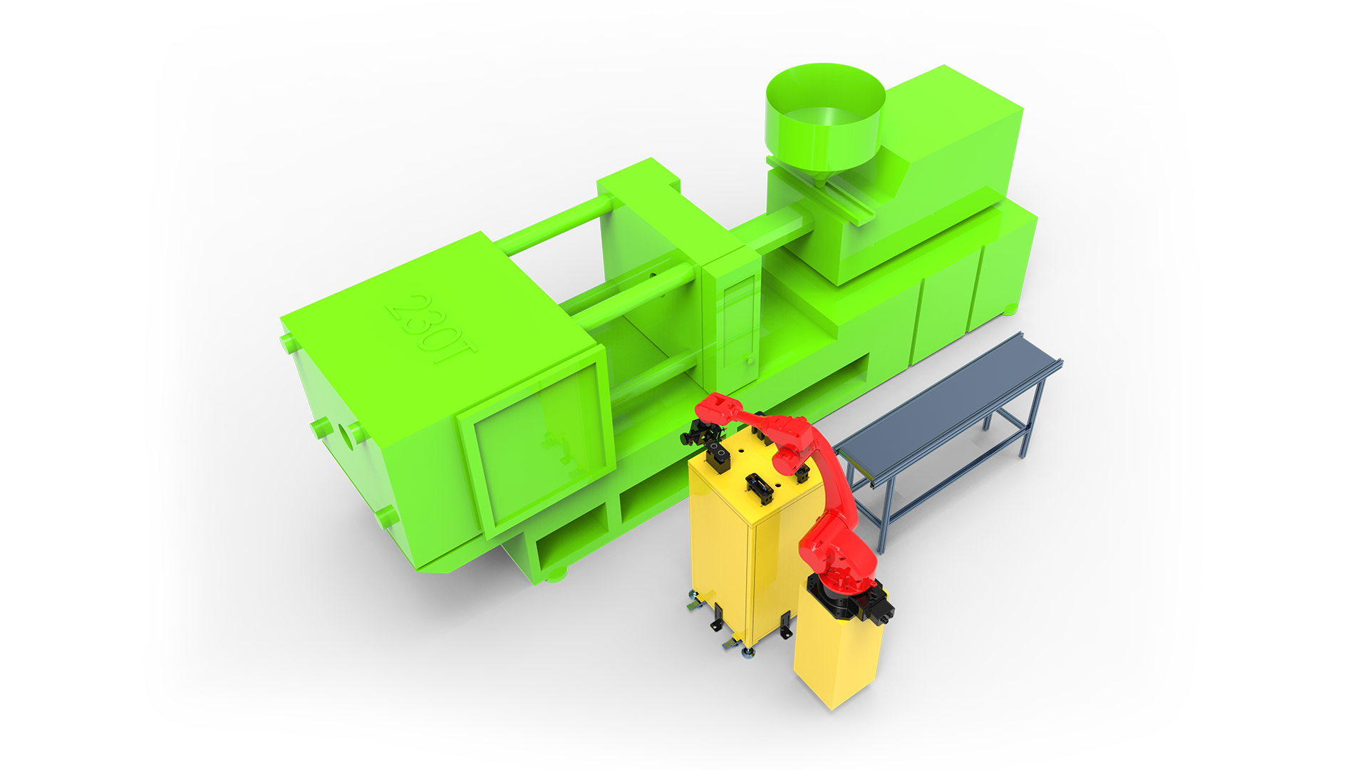
Edge grinding of a cover component using a BRTIRUS1510A six-axis robot platform.
A practical selection sequence
- Define the finish specification and the acceptance criteria for the edge.
- Characterise the part variation — dimensional tolerance and surface condition.
- Choose the abrasive sequence and the tooling.
- Determine the force-control strategy.
- Calculate total moving payload, including gripper and tooling.
- Size the robot so the finishing path sits inside the working envelope, not at its edge.
- Confirm the part presentation method and fixturing.
- Confirm safety, control and integration requirements with the upstream process.
Steps 1 through 4 usually determine the answer to step 6. Shops that start with the robot model often end up re-specifying it.