Robot Cell Electrical & Control Cabinet Integration for CNC Machine Tending: Layout, Cabling and Signal Handshaking

Why the electrical cabinet decides whether your robot cell works
Most machine tending projects are not won or lost on the robot arm. They are won or lost on the things around it: where the control cabinet sits, how the cables reach the machine, and whether the CNC and the robot can actually talk to each other reliably at 3 a.m. on a Tuesday.
A robot cell is a system. The arm is one component. The electrical enclosure, the cable routing, the safety circuit and the signal handshake between the machine tool and the robot controller are what turn a robot into a production asset.
This guide covers the electrical and control integration layer of a CNC machine tending cell — the part that is usually under-planned in the quotation stage and over-discussed during commissioning.
The customer problem: integration is where schedules slip
If you are specifying a machine tending cell, the symptoms are familiar:
- The robot was selected correctly, but the cabinet arrived and there was nowhere sensible to put it.
- Power and signal cables were routed after the fact, across walkways or under the machine, and now nobody wants to service them.
- The CNC door interlock, chuck clamp confirmation and robot gripper signal were wired as an afterthought, producing intermittent faults that are hard to reproduce.
- The controls engineer who understood the handshake has left the project.
None of these are robot problems. They are cell architecture problems — and they are cheapest to solve at the layout stage.
Why automation: what a well-integrated cell actually delivers
Automation in machine tending is not primarily about removing an operator. It is about making the machining process repeatable:
- Consistent part presentation. The same gripper, the same insertion depth, the same clamping sequence on every cycle.
- Repeatable production across shifts. Cycle time and part quality stop depending on which shift is running.
- Long-term cost structure. Labor is redirected from loading parts to monitoring multiple machines, tooling and quality.
- Flexibility. A cell that can be re-tasked to a different part family without rewiring the plant.
All four of these depend on the electrical and control layer being designed as part of the cell, not appended to it.
Solution logic: how a machine tending cell is actually put together
A CNC tending cell is assembled in layers. Getting the sequence right avoids most commissioning problems.
Layer 1 — Cell layout and floor space planning
The starting constraint is usually the machine, not the robot. Work outward from the machine door:
- Machine door position and opening direction define the robot's approach envelope.
- Robot mounting position is set so the arm can reach the chuck or fixture, the part magazine or conveyor, and the gripper change or drop-off station without singularities at the extremes.
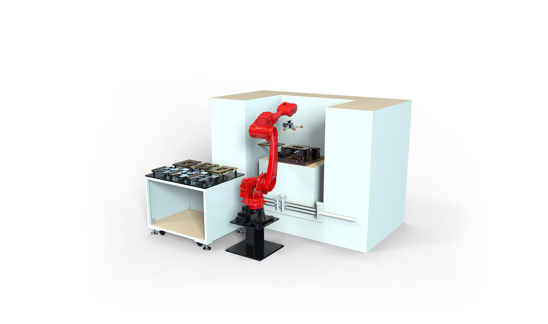
- Control cabinet position is then placed where it does not block operator access to the machine, does not sit in the chip or coolant path, and still allows the door to swing fully open.
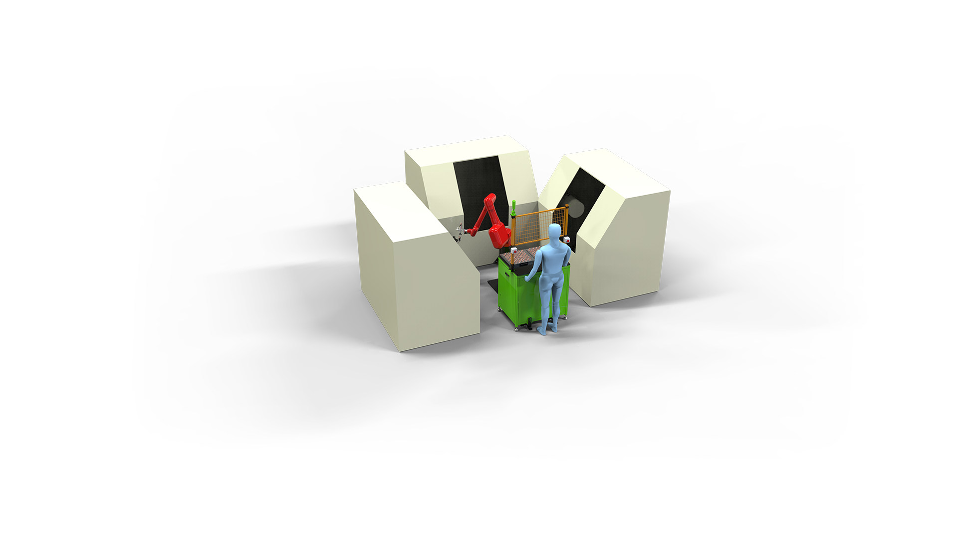
A layout that works for a single machine often does not scale to a one-robot-to-multiple-machine arrangement. In multi-machine tending, the cabinet placement and cable route become the dominant layout constraint, because the robot now travels or reaches across a longer working envelope.
Layer 2 — Cabinet selection and placement
Two options dominate machine tending installations:
- Floor-standing cabinet, placed beside or behind the cell. More internal volume, easier to service, but consumes floor space and needs its own cable route.
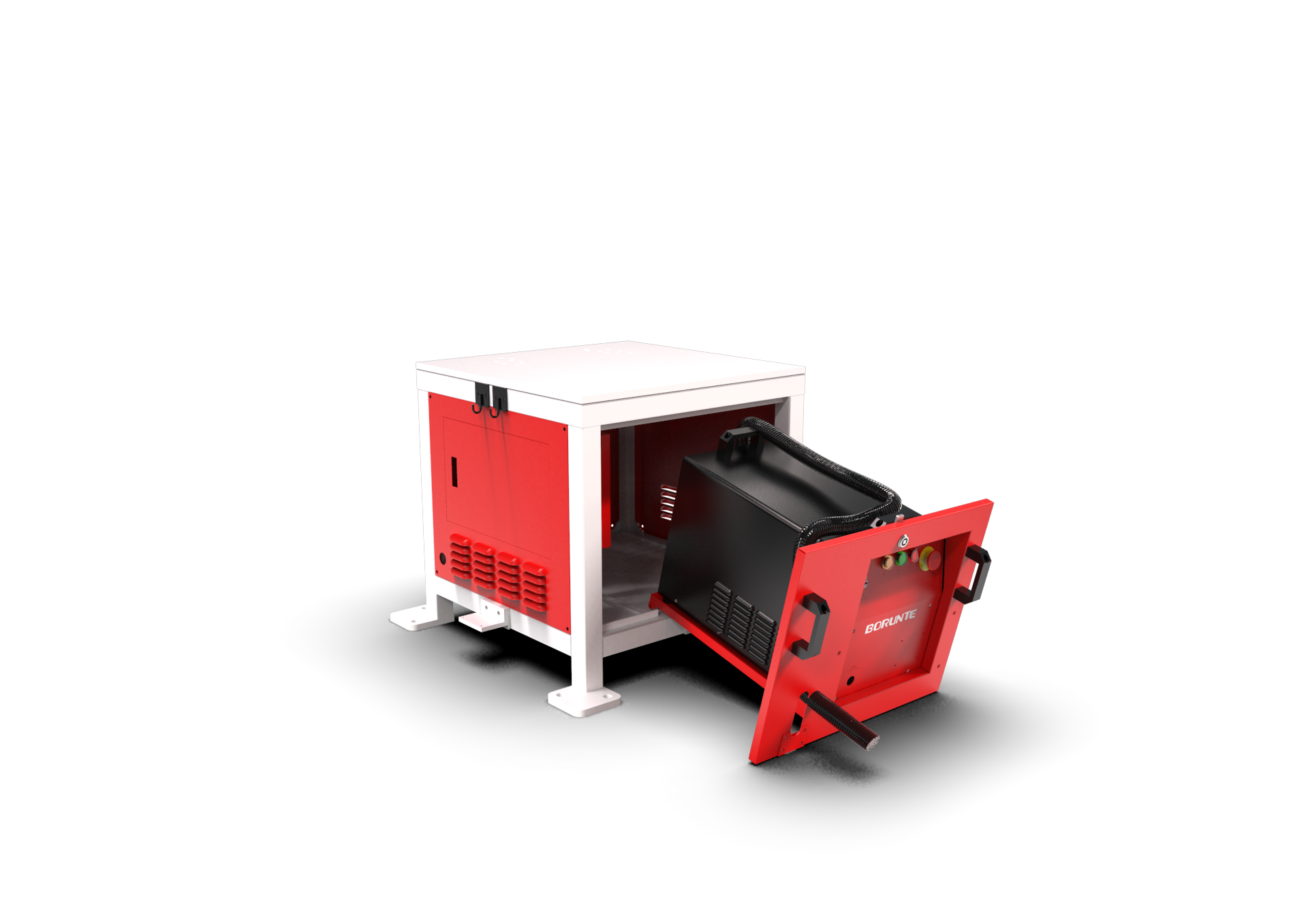
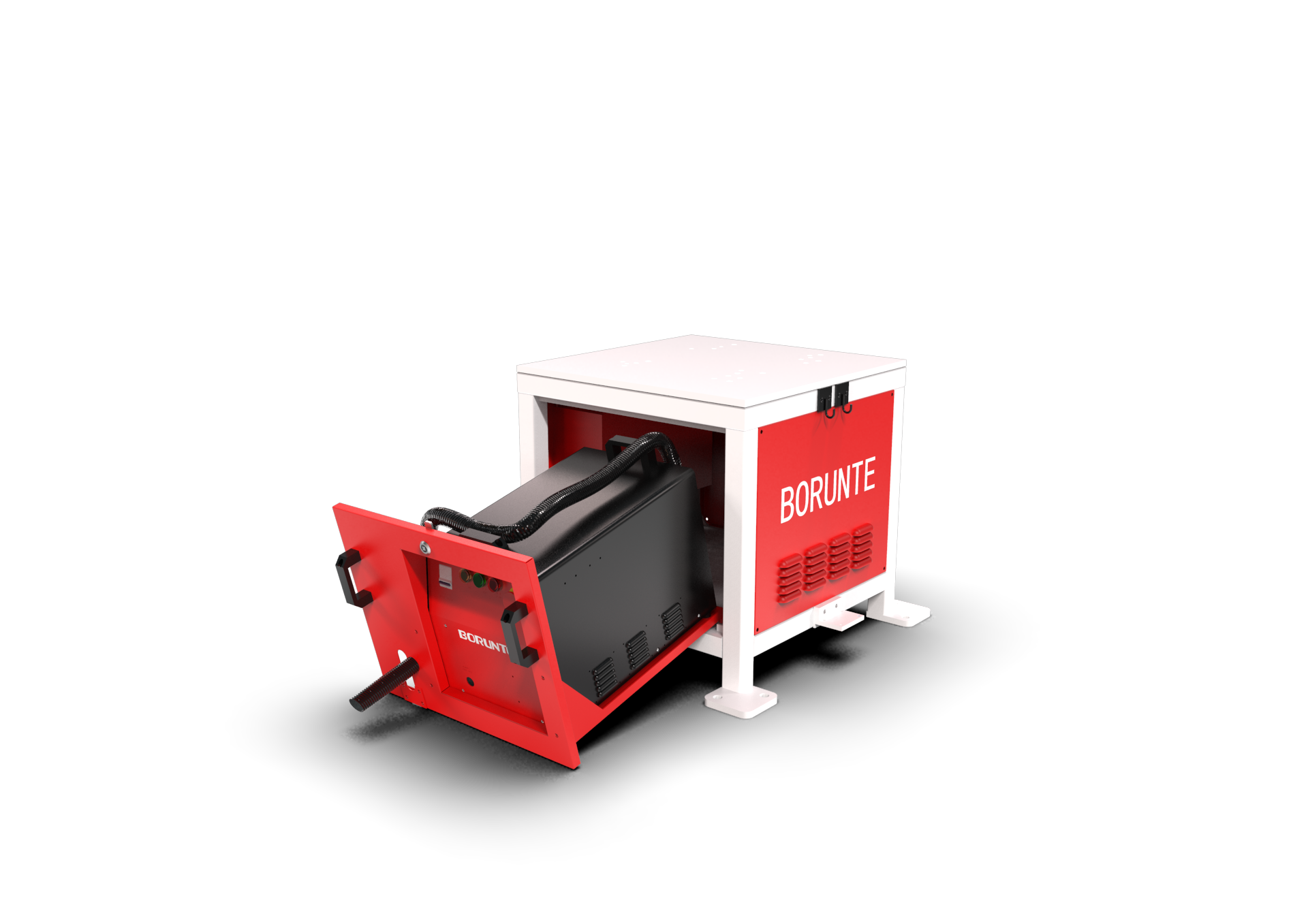
- Base-mounted cabinet, integrated under or into the robot base structure. Recovers floor space, shortens motor and encoder cable runs, and keeps the electrical enclosure inside the cell footprint.
A base-mounted enclosure is a structural and thermal decision as much as an electrical one. It has to manage heat from servo drives, keep IP protection against coolant mist and chips, and still allow an engineer to open it and work inside. This is one of the areas where the enclosure is best treated as part of the cell design rather than a purchased box.
Layer 3 — Cable management
Cable routing is where most cells look fine in the quotation drawing and fail in reality. The principles:
- Separate power and signal. Servo drive power, spindle power and 24 V signal wiring should not share a bundle or a tray section. Crosstalk on encoder and sensor lines produces faults that look like mechanical problems.
- Protect the dress pack. Robot arm cabling, gripper air lines and sensor wiring should be routed with strain relief and a defined flex point, not zip-tied to whatever is nearby.
- Plan for service. Every cable run should be reachable. A cable that can only be replaced by dismantling the cell is a future downtime event.
- Respect the machine tool environment. Coolant, chips and vibration are present. Routing under the machine or through the chip conveyor area is a common and avoidable mistake.
Layer 4 — Machine-to-robot signal handshaking
The handshake is the logical contract between the CNC and the robot controller. In a typical tending cycle it covers, at minimum:
- Robot requests machine access (door open permitted)
- Machine confirms door open and spindle stopped
- Robot confirms part gripped / chuck released
- Machine confirms clamp closed and cycle start permitted
- Fault and emergency-stop propagation in both directions
How this handshake is physically implemented depends on what the machine tool and the robot controller each support. The practical options are discrete I/O, a fieldbus link, or a combination.
Key selection factors: comparison of handshake and cabinet approaches
The table below compares the common integration approaches for the electrical and control layer of a machine tending cell. It is a general engineering comparison, not a statement about any specific machine tool or controller.
| Approach | Typical wiring | Commissioning effort | Flexibility / re-tasking | Best suited to |
|---|---|---|---|---|
| Discrete 24 V digital I/O handshake | Point-to-point wiring per signal | Low per signal, grows with signal count | Limited — adding a signal means adding a wire | Simple cells, single machine, few interlocks |
| Native fieldbus link (e.g. Modbus TCP, CAN) | Single network cable plus power | Higher upfront, lower per added signal | Good — signals are configured, not wired | Cells with many interlocks or multiple machines |
| Fieldbus via protocol gateway / converter | Network cable to gateway, then to controller I/O | Moderate — gateway configuration is the critical step | Good, with one extra device to maintain | Mixed-vendor cells where machine and robot do not share a native bus |
| Base-mounted cabinet, integrated enclosure | Short internal runs to robot, single feed to cell | Depends on enclosure design and thermal plan | Neutral — layout benefit, not a protocol benefit | Cells where floor space is the binding constraint |
| Floor-standing cabinet, external placement | Longer runs from cabinet to robot and machine | Lower enclosure design effort | Neutral | Cells with available floor space and easier service access |
Robot-side factors that affect the electrical design
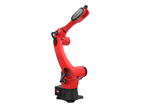
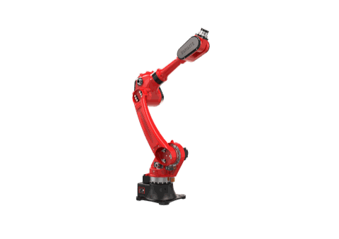
The robot model determines payload, reach, power draw and mounting, which in turn drive cabinet sizing and cable routing. Two models commonly used in CNC tending:
| Specification | BRTIRUS1510A | BRTIRUS1820A |
|---|---|---|
| Type | 6-axis industrial robot | 6-axis industrial robot |
| Payload | 10 kg | 20 kg |
| Arm reach | 1587 mm | 1895 mm |
| Repeatability | ±0.05 mm | ±0.05 mm |
| Robot weight | 152 kg | approx. 230 kg |
| Power capacity | 5.06 kVA | 5.87 kVA |
| CE conformity | Yes (2006/42/EC, 2014/35/EU) | Yes (2006/42/EC, 2014/35/EU) |
| Explosion-proof variant | Not available | Not available |
Specifications as published in the BORUNTE selection manual. Robots are supplied by BORUNTE; YGT Robot integrates them into machine tending cells.
Two practical consequences:
- Payload and reach determine whether the cell is a single-machine or multi-machine layout, which changes the cabinet placement and cable length budget.
- Power capacity (5.06 kVA vs 5.87 kVA) feeds directly into the cell's electrical supply sizing, breaker selection and heat load inside the enclosure.
Communication capability: what is native and what needs a gateway
On the robot controller side, the following interfaces are available natively:
- Modbus RTU
- Modbus TCP
- CAN
- Digital I/O
For machine tools or plant networks that use other protocols — Profinet, EtherCAT, CC-Link or DeviceNet — a protocol gateway or converter can bridge to the robot's Modbus / CAN / I/O interfaces. This is a normal and well-established integration approach, but the gateway configuration and signal mapping need to be confirmed against the specific machine tool and controller combination before the cell is built.
If your CNC uses a fieldbus that is not native to the robot controller, the integration path is a gateway — and the exact mapping should be confirmed with the cell integrator during design, not during commissioning.
YGT experience: what we see on machine tending projects
YGT Robot integrates industrial robots into machine tending cells, including CNC tending configurations built around BRTIRUS1510A and BRTIRUS1820A platforms. Our work sits in the layer between the machine tool and the robot: cell layout, enclosure and cabinet integration, cable routing, gripper and end-effector selection, and the signal handshake that makes the cycle repeatable.
A few patterns from that work:
- The cabinet position is usually decided too late. By the time the enclosure is ordered, the floor plan is fixed and the cabinet ends up somewhere it should not be.
- Handshake signals are under-specified. Teams agree on "the robot loads the part" but not on who confirms the chuck is closed, and in what order. Writing the signal list before the wiring diagram prevents most of this.
- Multi-machine cells change the electrical design, not just the robot program. A one-robot-to-three-machine arrangement has a different cable route and a different fault-recovery logic than a single-machine cell.
A practical sequence for specifying the electrical layer
If you are sourcing a machine tending cell, this order of decisions avoids most rework:
- Fix the machine tool interface: which signals exist, and how they are exposed (I/O, fieldbus, or both).
- Decide the handshake protocol before the cabinet is sized.
- Set the robot mounting position from the machine door and part flow.
- Place the cabinet — base-mounted or floor-standing — based on remaining floor space and service access.
- Design the cable route with power and signal separation, service access, and the machine environment in mind.
- Size the electrical supply from the robot power capacity plus gripper, sensors and any positioner or conveyor in the cell.
- Only then finalize the enclosure.
FAQ
Can the robot controller connect directly to a CNC that uses Profinet or EtherCAT? Not natively. The robot controller supports Modbus RTU, Modbus TCP, CAN and digital I/O natively. Profinet, EtherCAT, CC-Link and DeviceNet can be bridged through a protocol gateway or converter. The specific mapping depends on the machine tool and should be confirmed during cell design.
Is a base-mounted electrical cabinet better than a floor-standing one? It depends on what is constrained. A base-mounted enclosure recovers floor space and shortens cable runs to the robot, but it places the drives inside the cell environment and requires more attention to heat dissipation, IP protection and service access. A floor-standing cabinet is easier to service and design, but needs floor space and a longer cable route.
How many signals does a typical machine tending handshake need? It varies with the machine, but a basic cycle usually covers door open/closed, spindle stopped, clamp open/closed, part present, cycle start permitted, and fault and emergency-stop propagation in both directions. The exact list should be written before the wiring diagram.
Can one robot tend three CNC machines? Yes — one-robot-to-three-machine tending is an established configuration, and both BRTIRUS1510A and BRTIRUS1820A platforms are used in that arrangement. The electrical design changes: longer cable routes, more handshake logic, and different fault-recovery behaviour compared with a single-machine cell.
Do these robots have an explosion-proof variant? No. Neither BRTIRUS1510A nor BRTIRUS1820A has an explosion-proof version. If your application requires explosion protection, that needs to be addressed at the robot selection stage.
What should be confirmed before ordering the cabinet? The handshake protocol and signal list, the robot mounting position, the required electrical supply, the cable route, and service access. Ordering the enclosure before these are fixed is the most common cause of layout rework.
Related products
- BRTIRUS1510A six-axis industrial robot — 10 kg payload, 1587 mm reach, commonly used in CNC tending cells.
- BRTIRUS1820A six-axis industrial robot — 20 kg payload, 1895 mm reach, suited to heavier part handling and multi-machine tending.
Next step
If you are planning a machine tending cell and the electrical and control layer is still open, the most useful thing to do is write the signal list and the cabinet placement constraint down before the enclosure is ordered.
Share your machine tool interface, part envelope and floor plan with our engineering team. We will review the cell layout, the handshake approach and the cabinet integration options for your specific configuration — including whether a base-mounted enclosure or a floor-standing cabinet fits your floor space better.