Six-Axis Robot Tending for CNC Lathes: A Selection Guide for One-to-Many Layouts, Bar Feeding, and Payload/Reach/Cycle Matching

Why CNC Turning Cells Are the Next Automation Frontier
Most machine shops automated the easy part first: a bar feeder on a lathe, a chip conveyor, maybe a gantry loader on one machine. What remains manual is the part that ties the cell together — moving workpieces between machines, orienting them, loading chucks, and keeping three or four spindles fed at the same time.
A single operator walking between three CNC lathes is a familiar picture. It is also a picture that hides a lot of cost: idle spindle time while the operator is at another machine, inconsistent chuck loading force, and a hard ceiling on how many machines one person can realistically tend.
Six-axis robot tending changes that ceiling. But the selection process is not "pick the biggest robot." It is a matching problem between three things: how many machines you want to serve (layout), how the workpiece arrives (feeding method), and what the robot can physically carry and reach within the required cycle time.
This guide walks through that matching problem for two widely used six-axis models — the BRTIRUS1510A and BRTIRUS1820A — in the context of retrofitting existing CNC turning and machining lines.
The Customer Problem: What Actually Breaks in a Manual Tending Cell
Before choosing a robot, it helps to name the failure modes that drive the retrofit.
- Spindle idle time between operations. In a one-operator-to-three-machines setup, each lathe waits while the operator finishes at another. The wait is not constant — it depends on cycle length, part weight, and how far the operator has to walk.
- Chuck loading variability. Manual loading produces small variations in seating depth and clamping force. On tight-tolerance turning, that variation shows up as scrap or as rework at inspection.
- Difficult parts to handle manually. Castings, forgings, and heavy bar stock are awkward to lift repeatedly. Operator fatigue compounds the variability problem over a shift.
- Changeover friction. When a cell depends on manual handling, changing part families means re-teaching a person, not re-teaching a program. Setup time stays high.
These are the problems a robot tending unit is meant to solve. The selection question is how to size the robot so it actually solves them rather than creating a new bottleneck.
Why Automate: The Value Beyond Labor
It is worth being precise about what robot tending delivers, because "replace the operator" is an incomplete framing.
- Repeatable loading. A robot places the workpiece to the same position every cycle. For turning operations where seating depth affects dimensional results, this is a quality control mechanism, not just a labor saving.
- Continuous operation across machines. A robot can be programmed to service multiple machines in a fixed sequence, keeping spindles fed without the walking time that limits a human operator.
- Stable output over a full shift. Cycle-to-cycle consistency does not degrade toward the end of a shift.
- Flexibility through programming. Changing part families becomes a matter of loading a new program and, where needed, changing gripper jaws — rather than retraining an operator.
- Long-term cost structure. The economic case is usually built on reduced idle spindle time, reduced scrap, and the ability to run the cell with less direct labor attention — not on headcount reduction alone.
Solution Logic: How a One-to-Many Tending Cell Is Built
A CNC tending cell is a system, not a robot. The integration work sits in how the pieces connect.
Typical architecture for a one-to-three lathe cell:
- Feeding interface. Workpieces arrive either as bar stock (fed through the spindle or presented at a pick station) or as discrete blanks (billets, castings, forgings) presented on a tray, conveyor, or magazine.
- Pick station. The robot picks from a defined position. For bar work, this may be a bar feeder presenting to a pick point; for discrete parts, a locating nest or vision-assisted position.
- Robot transfer. The robot moves the workpiece to the chuck, orients it, and loads it. After machining, it unloads and either places the finished part on an output conveyor or returns it for a second operation.
- Machine interface. The robot controller communicates with each CNC via I/O or fieldbus to open/close the chuck, confirm cycle complete, and trigger the next operation.
- Safety and guarding. The cell is enclosed or interlocked so that robot motion and machine motion do not create a hazard.
The integration decisions that matter most are the pick station design, the gripper design (especially for bar and round stock), and the machine-to-robot handshake. These determine whether the cell runs reliably at the intended cycle time.
Key Selection Factors
Payload
Payload is the total mass the robot wrist must carry: the workpiece, the gripper, and any adapter plate. For CNC tending, the workpiece is often the smaller part of that total — a double-jaw gripper for handling both raw and finished parts can weigh several kilograms on its own.
| Robot Model | Rated Payload | Arm Reach | Repeatability | Approx. Mass |
|---|---|---|---|---|
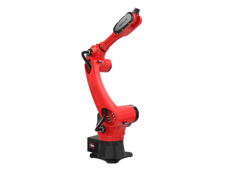
| BRTIRUS1510A | 10 kg | 1,587 mm | ±0.05 mm | 152 kg |
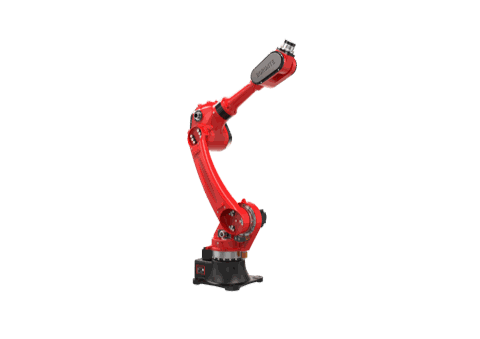
| BRTIRUS1820A | 20 kg | 1,895 mm | ±0.05 mm | Approx. 230 kg |
Specifications from BORUNTE selection catalog. YGT Robot integrates these models into CNC tending and other automation applications.
A practical rule: estimate workpiece mass, add gripper mass, add a margin for dynamic loads during acceleration. If the total approaches the rated payload, the robot will be operating near its limit, which affects cycle time and, over time, mechanical wear.
Arm Reach
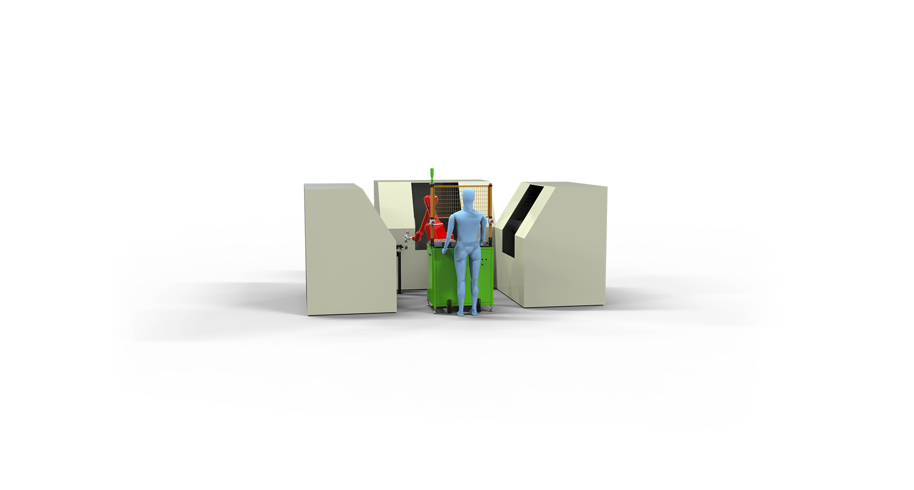
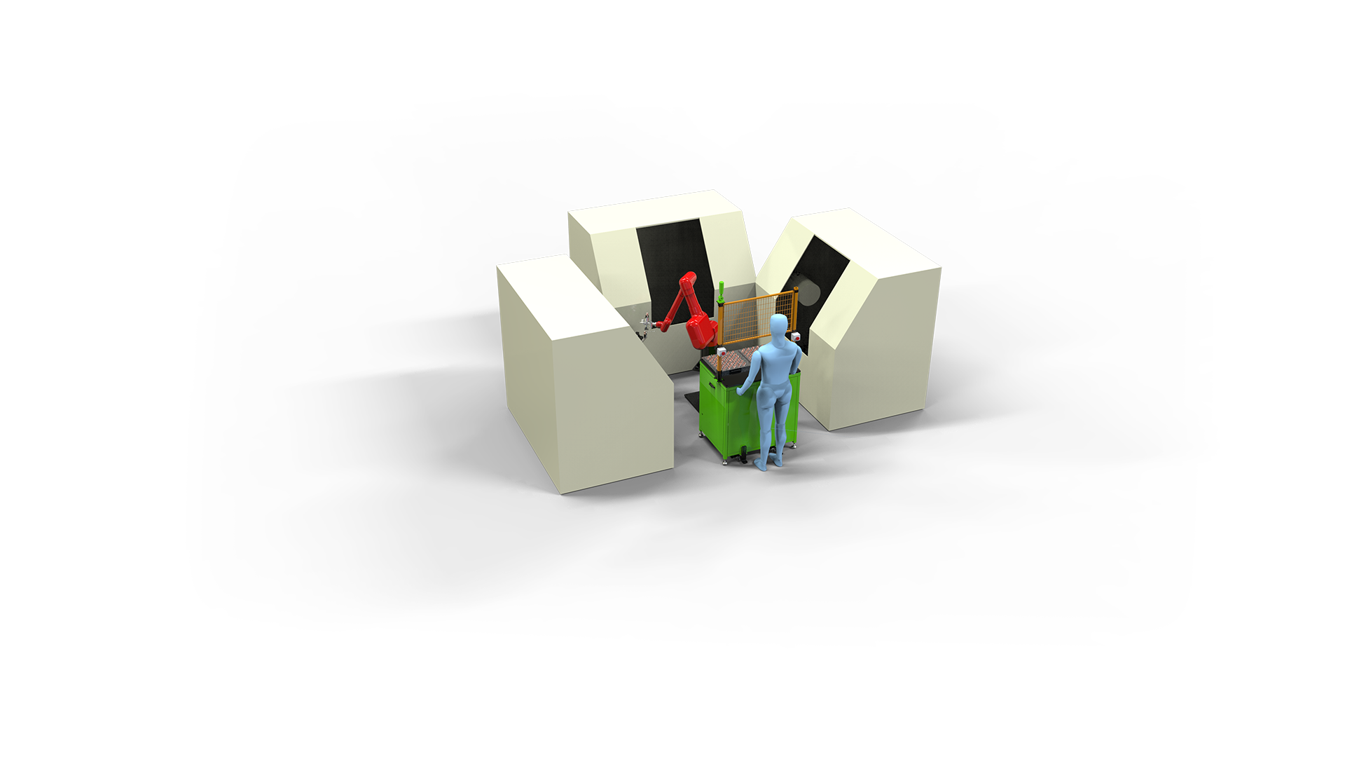
The reach must cover the full travel between the pick station, the chuck, and the unload position — plus the geometry of the machine enclosure. In a one-to-three layout, the robot is often mounted centrally, and reach determines whether it can serve all three machines from one base position or whether the layout needs to be arranged differently.
The BRTIRUS1510A at 1,587 mm and the BRTIRUS1820A at 1,895 mm differ by roughly 300 mm of reach. That difference can determine whether a central mounting position works for a given machine spacing, or whether the cell needs a different arrangement.
Cycle Time
Cycle time in a tending cell is not just the robot's transfer time. It includes:
- Pick time (including any grip confirmation)
- Transfer time (affected by reach and by how much the robot has to reorient)
- Load time (chuck approach, seating, clamp confirmation)
- Unload time
- Any waiting for machine cycle completion
For a one-to-three cell, the robot's total service time across three machines must fit within the combined machine cycle window. If the robot cannot complete a full round in the time available, one machine will wait — and the cell's output is limited by the robot, not the machines.
This is where payload and reach interact with cycle time: a heavier workpiece may require slower acceleration, and a longer reach may require more travel time. Matching the robot to the cell means checking that the required cycle can be met with the actual workpiece and gripper.
Feeding Method: Bar vs. Discrete Parts
The feeding method shapes the gripper and the pick station design.
- Bar stock is typically fed through the spindle or presented at a pick point. Gripping round bar requires a gripper that can handle cylindrical surfaces without slipping, and the robot must be able to insert the bar into the chuck or collet accurately.
- Discrete blanks (billets, castings, forgings) are presented on trays, conveyors, or magazines. These may require orientation before loading, and the gripper must handle the part geometry reliably.
- Mixed feeding — some machines running bar, others running blanks — is possible but increases the complexity of the pick station and the gripper design.
The feeding method also affects the payload calculation: a bar gripper and a billet gripper may have different masses, and the robot must be sized for the heavier case.
Machine Interface and Controller Compatibility
The robot must communicate with each CNC to coordinate loading and machining. This is typically done through digital I/O or a fieldbus connection. The specific interface depends on the CNC controller brand and model in the existing machines.
Because retrofits involve existing equipment, the interface question is often the first thing to resolve: what signals are available from each machine, and how will the robot controller use them?
Gripper Design for Round and Bar Stock
For CNC turning, gripper design is often the difference between a cell that runs and a cell that stops. Round stock can slip, and chuck loading requires a firm, repeatable grip. The gripper must also accommodate the part's orientation and any features that affect gripping.
Safety and Guarding
A tending cell combines robot motion with machine motion. Guarding, interlocking, and safe robot positioning are part of the system design, not an afterthought.
YGT Experience: Integration in Practice
YGT Robot's role in CNC tending projects is integration and application — selecting the appropriate robot platform for the cell, designing the pick station and gripper interface, and coordinating the machine-to-robot communication. The robot models themselves are supplied by BORUNTE, and their specifications are used as the basis for selection.
One example of this work is a one-to-three CNC tending project using the BRTIRUS1510A, where a single six-axis robot serves three CNC machines. The project illustrates the layout and integration decisions described above: central mounting, pick station design, and machine interface coordination.
For shops considering a retrofit, the practical starting point is a review of the existing machines, the part families, and the feeding method. From there, the robot selection follows from the payload, reach, and cycle time requirements.
FAQ
Q: How do I decide between the BRTIRUS1510A and BRTIRUS1820A for CNC tending?
A: Start with the workpiece and gripper mass. If the total is comfortably within 10 kg and the reach requirement is within 1,587 mm, the BRTIRUS1510A is the smaller, lighter option. If the workpiece or gripper is heavier, or the layout requires more reach, the BRTIRUS1820A at 20 kg payload and 1,895 mm reach provides more margin. The decision should be based on the actual cell layout and the heaviest part to be handled.
Q: Can one robot serve three CNC machines?
A: Yes, this is a common one-to-many layout. The robot is typically mounted centrally and programmed to service each machine in sequence. The key constraint is cycle time: the robot's total service time across all machines must fit within the combined machine cycle window. Reach also matters — the robot must be able to cover the distance between the pick station and each machine's chuck.
Q: What is the difference between bar feeding and blank feeding for robot tending?
A: Bar feeding presents round stock, often through the spindle or at a pick point, and requires a gripper that handles cylindrical surfaces. Blank feeding presents discrete parts on trays, conveyors, or magazines, and may require orientation before loading. The feeding method affects both the gripper design and the pick station layout.
Q: How is cycle time calculated for a tending cell?
A: Cycle time includes pick, transfer, load, and unload times, plus any waiting for machine cycle completion. For a one-to-three cell, the robot's total service time across three machines must fit within the available window. Payload and reach affect transfer time, so the calculation should use the actual workpiece and gripper masses.
Q: What communication is needed between the robot and the CNC machines?
A: The robot controller and each CNC typically exchange signals for cycle start, chuck open/close, and cycle complete. The specific interface depends on the CNC controller model. In a retrofit, the available signals from the existing machines are the starting point for the interface design.
Q: Does YGT Robot manufacture the robots?
A: No. YGT Robot integrates BORUNTE industrial robots into CNC tending and other automation applications. The robot specifications referenced in this guide are from the BORUNTE selection catalog.
Related Products
- BRTIRUS1510A Six-Axis Robot
- BRTIRUS1820A Six-Axis Robot
Related Cases
- One-to-Three CNC Tending Project with BRTIRUS1510A
Next Step
If you are planning a CNC tending retrofit, the most useful first step is a review of your existing machines, part families, and feeding method. From there, the robot selection follows from payload, reach, and cycle time.
YGT Robot's engineering team can help assess your cell layout and identify the appropriate robot platform for your application.