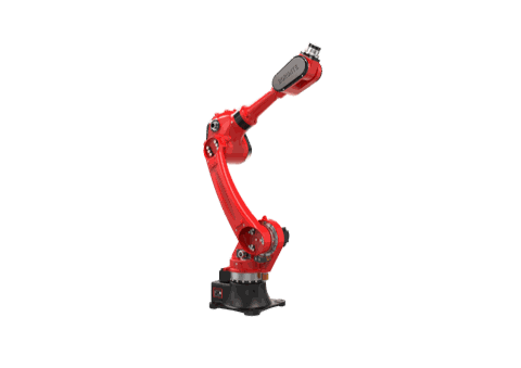
Sourcing FAQ: Specifying a Robot Cell for Tapping Machine and Secondary Threading Operations — Part Transfer, Spindle Orientation, Chip/Coolant Exposure, Torque-Reactive Fixturing, and Cycle Matching with BRTIRUS1820A


Why tapping cells are specified differently from general machine tending
Tapping and secondary threading look like simple operations from a distance. In practice they are one of the more demanding machine-tending applications to specify, because three things happen at the same time: the tool is rotating, the workpiece is being pulled by torque, and the cutting zone is producing chips and coolant.
A cell that works well for loading a press or a CNC lathe will not automatically work for a tapping machine. The sourcing questions are different. This FAQ walks through the ones that most often decide whether a tapping cell runs reliably or becomes a maintenance problem.
Customer problem: what buyers actually struggle with
Process planners and procurement teams evaluating robotic tending for tapping usually raise the same set of concerns:
- Part transfer into a rotating spindle. The robot has to place the part in a position where the tap can engage cleanly. Small angular errors that would be harmless elsewhere translate into cross-threading or broken taps here.
- Spindle orientation. A tapping spindle is not a passive fixture. The robot and the machine have to agree on where the spindle is and when the part is safe to release.
- Chips and coolant. Tapping generates fine, stringy chips and a wet environment. Grippers, cabling, and the robot wrist all live in that zone.
- Torque reaction. When the tap bites, the part wants to rotate. Whatever holds the part has to resist that without letting the part move in the gripper.
- Cycle matching. Tapping is fast. If the robot cannot keep up, the machine sits idle and the business case weakens.
Why automate a tapping or secondary threading cell at all
Automation here is not primarily about headcount. The value shows up in four places:
- Consistent thread quality. A robot presents the part the same way on every cycle, which reduces the variation that causes cross-threading and tap breakage.
- Repeatable production. Tapping cells are often the bottleneck in a multi-step process. A robot keeps the machine fed at a steady rate instead of in batches.
- Long-term cost reduction. Broken taps, scrapped parts, and rework are expensive. Reducing them compounds over the life of the cell.
- Production flexibility. A programmable cell can be re-tasked when part families change, which is harder to do with dedicated hard automation.
Solution logic: how a tapping tending cell is actually put together
A tapping machine tending cell is a system, not a robot. The integration work sits in how the pieces talk to each other:
- Robot platform selection — payload, reach, and repeatability matched to the part and the machine layout.
- End-of-arm tooling — gripper design that resists torque reaction and survives chips and coolant.
- Part presentation — infeed arrangement (tray, conveyor, or feeder) that puts the part in a known, repeatable position.
- Machine interface — handshake between robot and tapping machine covering spindle state, clamp state, and safe-to-load conditions.
- Chip and coolant management — airflow, shielding, and drainage around the gripper and wrist.
- Safety and guarding — cell fencing, interlocks, and light curtains sized to the actual reach envelope.
This is where the integration role matters. The robot is one component; the cell performance comes from how tooling, presentation, machine interface, and safety are designed around the specific tapping process.
Key selection factors
The table below summarizes what to specify and why it matters for tapping specifically.
| Factor | What to specify | Why it matters in tapping / secondary threading |
|---|---|---|
| Payload | Part weight + gripper weight + safety margin | Tapping often involves heavier fixtures or multi-part grippers; under-specifying payload limits gripper options |
| Working range (arm reach) | Distance from robot base to load/unload positions, plus any tray or conveyor | Determines whether one robot can serve the machine and the part presentation area |
| Repeatability | Positioning accuracy at the wrist | Directly affects how consistently the part seats before the tap engages |
| Spindle orientation handling | Whether the cell reads spindle position or uses a fixed-orientation load position | Prevents loading into a rotating or mis-indexed spindle |
| Torque-reactive fixturing | Gripper clamping method and any anti-rotation feature | Resists the part rotating when the tap bites |
| Chip and coolant exposure | IP rating of wrist/gripper, cable routing, drainage | Fine chips and coolant shorten the life of unprotected tooling |
| Cycle matching | Robot cycle time vs. machine cycle time | Determines whether the machine is fed continuously or waits |
| Controller compatibility | I/O and communication with the tapping machine | The handshake is what makes the cell safe and repeatable |
| Safety integration | Guarding, interlocks, reach envelope | Required for any cell where a robot and a machine share a load position |
| After-sales support | Spares, service response, programming support | Tapping cells are production-critical; downtime is costly |
A note on the reference robot: BRTIRUS1820A
For readers using BRTIRUS1820A as the reference platform, the confirmed specifications relevant to this discussion are:
- Type: six-axis robot
- Payload: 20 kg
- Arm reach: 1895 mm
- Repeatability: ±0.05 mm
- Weight: approx. 230 kg
- Power capacity: 5.87 kVA
- Certification: CE (machinery 2006/42/EC and low voltage 2014/35/EU, ICG, conformity verification DPWD/03/0646/2025)
- Explosion-proof: not supported on this model (the BORUNTE range includes one explosion-proof model, BRTIRSE2013F)
These figures come from the BORUNTE selection catalog. They are the starting point for a cell specification, not the whole answer — the tooling, presentation, and machine interface are what determine whether the cell performs in a tapping application.
YGT experience: what integration work looks like in practice
YGT Robot (Guangdong Yigaite Intelligent Technology Co., Ltd.) works as a system integrator and application solution provider for robotic automation. In tapping and secondary threading applications, that means:
- Selecting a robot platform based on the part, the machine, and the layout — not the other way around.
- Designing end-of-arm tooling that accounts for torque reaction, chip exposure, and coolant.
- Building the handshake between the robot and the tapping machine so that loading only happens when the machine is in a safe state.
- Supporting the cell on site after commissioning, because tapping cells are production-critical.
Our confirmed application scope covers handling, machine loading/unloading, palletizing, spraying, and welding. For applications outside that scope — including deburring, grinding, polishing, dispensing, vision sorting, laser cutting, and assembly — the correct answer is to confirm with our engineers rather than assume.

FAQ
Q: How does the robot know the tapping spindle is in a safe position to load?
The cell needs a handshake between the robot controller and the tapping machine. Typically this means the machine signals spindle state and clamp state, and the robot only enters the load position when the machine confirms it is safe. The exact signal set depends on the tapping machine's controller and I/O. This is one of the first things to confirm during cell specification, because it determines the wiring and the PLC logic.
Q: What repeatability do I need for tapping?
Repeatability affects how consistently the part seats before the tap engages. For reference, BRTIRUS1820A is specified at ±0.05 mm. In practice, the more important number is often the repeatability of the part presentation — the tray or feeder — because the robot can only place the part as accurately as it picks it up.
Q: How do I deal with torque reaction when the tap bites?
The part wants to rotate when the tap engages. Two things help: a gripper that clamps the part firmly enough to resist that rotation, and a load position that gives the part a positive mechanical stop against the machine fixture. If the part is only held by friction in the gripper, torque reaction will eventually cause slippage and thread quality problems.
Q: What about chips and coolant?
Tapping produces fine, stringy chips and a wet cutting zone. The practical measures are: route cables away from the chip path, choose a gripper and wrist configuration that tolerates coolant exposure, and provide drainage so chips and fluid do not accumulate on the tooling. The specific IP rating and shielding approach depend on the machine and the coolant used.
Q: Can one robot serve more than one tapping machine?
It depends on the layout and the cycle times. With an arm reach of 1895 mm on BRTIRUS1820A, the reach envelope may cover more than one load position, but the deciding factor is usually cycle matching — whether the robot can serve both machines without either one waiting. This is a layout and cycle-time study, not a robot-specification question alone.
Q: How do I match robot cycle time to the tapping machine cycle time?
The robot cycle time includes pick, transfer, load, wait for machine, unload, and return. The machine cycle time is the tapping operation itself. If the robot cycle is longer than the machine cycle, the machine will wait. The specification work is to measure both, then decide whether one robot per machine, one robot for two machines, or a different part presentation arrangement gives the best utilization.
Q: Does BRTIRUS1820A support explosion-proof environments?
No. BRTIRUS1820A does not support explosion-proof operation. Within the BORUNTE range, only BRTIRSE2013F is an explosion-proof model. If your tapping cell is in a hazardous area, that constraint has to be addressed at the platform selection stage.
Q: What certifications does BRTIRUS1820A carry?
BRTIRUS1820A carries CE certification, covering machinery (2006/42/EC) and low voltage (2014/35/EU), with conformity verification DPWD/03/0646/2025 issued by ICG. This is relevant for cell compliance documentation in European and other CE-recognized markets.

Related products
Next step
If you are specifying a tapping or secondary threading cell, the useful conversation is not "which robot" but "what does the cell have to do." Share the part, the tapping machine, the required cycle time, and the shop layout, and our engineers can work through the transfer method, fixturing approach, and machine interface with you.