Sourcing FAQ: Specifying Six-Axis Robot Cells for High-Cavitation Injection Molding — Sprue Picking, Insert Loading and Take-Out Boxing

Why high-cavitation molding changes the robot specification
In a low-cavitation tool, a robot cell is often judged on whether it can reach the part and pull it out. In a high-cavitation tool — 16, 32, 48 cavities and beyond — the robot is no longer a peripheral device. It sits inside the takt time of the press, and every decision made about the end-of-arm tooling, the robot's reach envelope, and the boxing pattern feeds back into whether the press can run at its designed cycle.
This article is written for the people who actually have to specify and sign off on these cells: purchasing engineers, automation integrators, and manufacturing engineers. It is organized as a sourcing FAQ, because that is how the questions usually arrive — one at a time, each one capable of stopping a project.
The customer problem, stated plainly
A molder running high-cavitation tools typically faces a cluster of problems that arrive together:
- Sprue and runner removal is a bottleneck. On multi-cavity tools the sprue is often the first thing out and the last thing handled. If the robot cannot separate sprue from parts reliably, an operator ends up standing at the press.
- Insert loading is a positioning problem, not a lifting problem. Metal inserts must land in the mold within a fraction of a millimeter, cycle after cycle, without marking the cavity.
- Take-out boxing is where cycle time quietly disappears. A robot that picks parts correctly but boxes them slowly simply moves the bottleneck downstream.
- Labor is unstable at the volumes these tools run. High-cavitation molding is a volume business; manual take-out at that volume is a staffing problem before it is a cost problem.
- Quality consistency matters more than speed. Short shots, scuffing, and dropped parts create scrap that scales with cavity count.
None of these are robot problems in isolation. They are cell problems, and the robot is one component of the answer.
Why automation, and where it actually pays
The case for automating a high-cavitation cell is not "robots are faster than people." At these volumes, a well-run manual cell can be fast. The case is different:
- Repeatability over a full shift. A robot does not lose positioning accuracy at hour nine. On insert loading, that matters more than peak speed.
- Stable quality at cavity count. Consistent take-out force and consistent boxing orientation reduce the handling-induced defects that multiply with cavity number.
- Long-run cost structure. The economics of a high-cavitation cell are dominated by uptime and scrap rate, not by the hourly rate of the operator being replaced.
- Flexibility across tools. A six-axis cell that is properly specified can be re-tooled for a different mold, which is difficult to achieve with hard automation.
Solution logic: how a cell is actually built
A high-cavitation take-out cell is assembled from four layers, and the integration work happens at the seams between them:
- The robot platform. Reach, payload, and repeatability must match the mold, the boxing station, and the insert feeder — not just the part.
- The end-of-arm tooling (EOAT). Sprue grippers, part grippers or vacuum cups, and insert-handling heads are usually combined on one wrist plate. EOAT design drives cycle time more than robot speed does.
- The press interface. The robot must be synchronized with mold opening, ejector stroke, and safety interlocks. This is where most integration risk lives.
- The downstream handling. Boxing, orientation, layer patterns, and any inspection or sprue/part separation.
YGT Robot's role in this kind of project is integration and application engineering: selecting a suitable robot platform, designing and building the EOAT and cell layout, and delivering the cell as a working system rather than as a robot on a pallet.
Key selection factors
Payload and EOAT weight
The rated payload must cover the EOAT plus the parts being handled, with margin. A multi-head EOAT that grips several parts at once, plus a sprue gripper and an insert head, adds up quickly. Under-sizing payload is one of the most common specification errors in high-cavitation cells, because the EOAT is often designed after the robot is chosen.
Working range and reach
Reach must cover the full path: from inside the mold, through the take-out trajectory, to the boxing station and the sprue chute. On large platen machines, the boxing station is often the constraint, not the mold. Reach should be checked against the worst-case tool, not the average one.
Repeatability
Repeatability matters most at the insert-loading step, where the insert must seat correctly without damaging the cavity. It also matters for boxing orientation when parts must be stacked in a specific pattern.
Cycle time and motion
Cycle time is not a robot specification — it is a cell specification. It includes mold-open wait, take-out, sprue separation, insert placement, boxing, and return. A robot with a faster rated cycle can still produce a slower cell if the EOAT is heavy or the boxing path is long.
Controller and communication compatibility
This is where sourcing questions most often stall. The robot controller must communicate with the injection molding machine and any peripheral equipment. Protocol and I/O requirements should be confirmed against the actual IMM brand and controller before the cell design is frozen.
Environment and certification
Standard molding environments are generally within the operating envelope of a general-purpose six-axis robot. Where the cell touches special atmospheres or regulatory requirements, certification should be verified explicitly rather than assumed.
After-sales and spares
For a cell running three shifts, response time and spare-part availability are part of the specification, not an afterthought.
Comparison: specification dimensions at a glance
| Selection factor | What it drives | Typical failure if under-specified |
|---|---|---|
| Payload | EOAT complexity, multi-part gripping | Slow motion, reduced accuracy, early wear |
| Working range | Boxing station layout, sprue chute position | Cell redesign, compromised layout |
| Repeatability | Insert loading, boxing orientation | Scrap, cavity damage, rework |
| Cycle time (cell-level) | Match to press takt | Press runs below designed rate |
| Controller / communication | IMM and peripheral integration | Integration delay, added hardware |
| Certification | Regulatory acceptance of the cell | Late-stage compliance issues |
| After-sales and spares | Uptime over the cell's life | Extended downtime, lost output |
A platform example: BRTIRUS1510A in a take-out and boxing cell
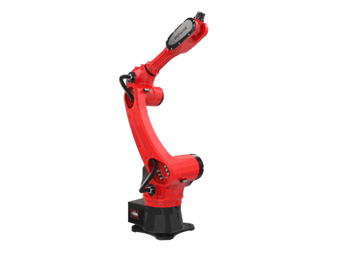
The BRTIRUS1510A is a six-axis robot platform with a 10 kg rated payload, 1587 mm arm reach, and ±0.05 mm repeatability, supplied with CE conformity verification. Those figures place it in the range that suits many mid-size injection molding take-out and boxing cells, where the EOAT is a combined sprue/part/insert head and the boxing station sits within a moderate radius of the press.
Two specification points are worth stating explicitly, because they are frequently assumed rather than checked:
- This platform is not explosion-proof. In the BORUNTE range, explosion-proof capability is provided by a different model. If your process requires it, that should be raised at the specification stage.
- Application scope should be confirmed, not assumed. Handling, loading/unloading, palletizing, spraying, and welding are within YGT Robot's declared application scope. Other applications — including deburring, polishing, gluing, vision sorting, laser cutting, and assembly — are not currently confirmed and should be discussed with YGT engineers before they are written into a specification.
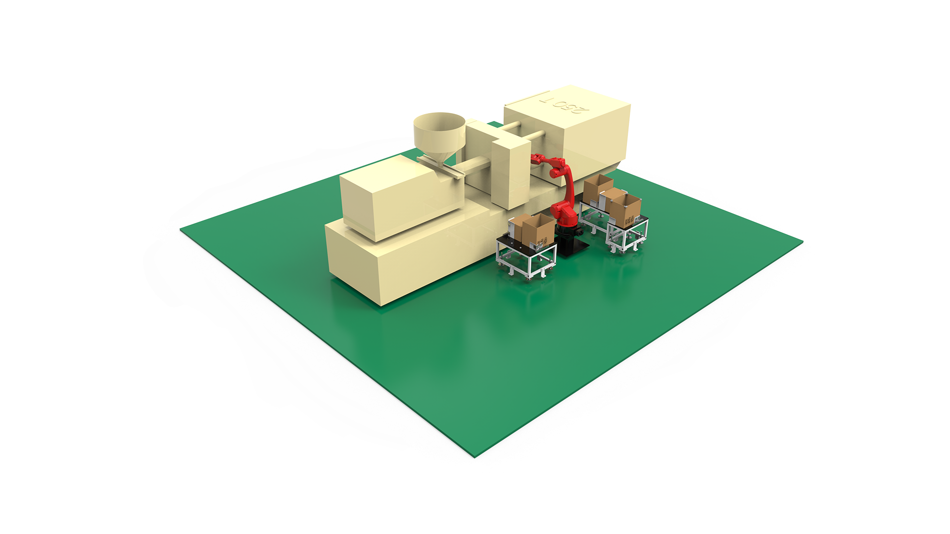
YGT Robot integrates BORUNTE robot platforms such as the BRTIRUS1510A into injection molding cells, and the integration work — EOAT, cell layout, press interface, and commissioning — is where the cell is made to perform. The robot model is a component of the solution; the cell is the deliverable.
YGT experience in injection molding take-out cells
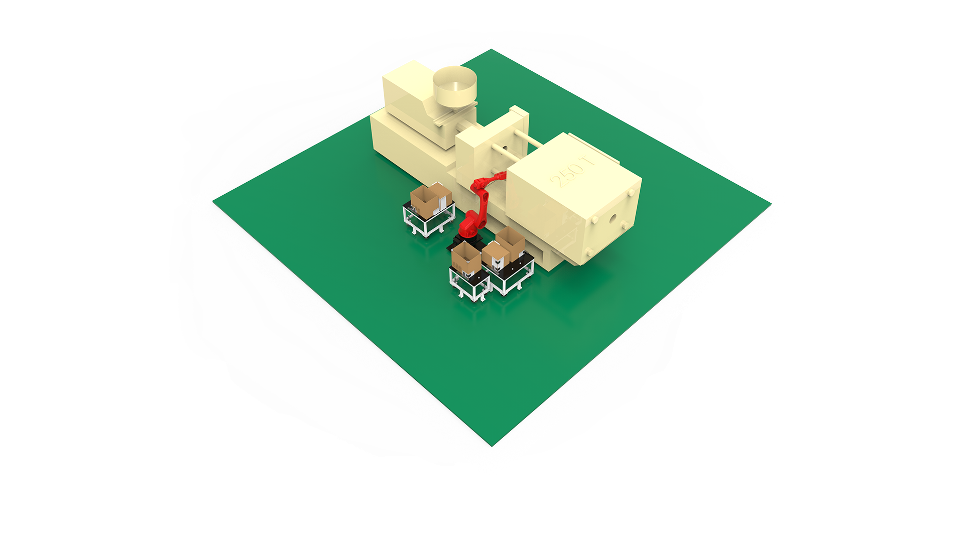
YGT Robot's injection molding work is centered on take-out, sprue handling, insert loading, and boxing cells built around six-axis robot platforms. In practice, the engineering effort in these projects concentrates in three places:
- EOAT design. Sprue gripping, part gripping, and insert handling are usually combined on a single wrist plate. Getting the weight distribution and the grip sequence right is what makes the cycle work.
- Press synchronization. The cell has to live inside the mold-open window. Timing, interlocks, and safe trajectories are designed around the specific press, not around a generic template.
- Boxing and downstream layout. Orientation, layer pattern, and the path between the mold and the boxing station are laid out together with the cell, because they determine whether the press can run at its designed rate.
This is integration work rather than catalog selection, and it is the part of the project that determines whether the cell performs as specified.
FAQ
Q: How do I choose between a sprue gripper and a vacuum cup for take-out?
It depends on what is being handled. Sprue and runner removal usually calls for a mechanical gripper, because the sprue is a rigid, irregular shape that vacuum does not hold reliably. Parts are often handled with vacuum cups where surface finish allows, or with mechanical grippers where the part geometry or surface requirements rule out vacuum. Many cells use both on the same EOAT.
Q: Can one six-axis robot handle sprue picking, insert loading, and boxing in the same cycle?
In many mid-size cells, yes — this is exactly why a combined EOAT is used. The constraint is cycle time, not the number of tasks. Each added task lengthens the motion sequence, so the cell must be checked against the press takt with all tasks included.
Q: What payload margin should I plan for?
The rated payload must cover the EOAT plus the parts, with margin for dynamic loads during acceleration. In practice, the EOAT is often heavier than expected once sprue grippers, part grippers, insert heads, and mounting plates are combined.
Q: How do I confirm the robot will communicate with my injection molding machine?
Communication compatibility should be confirmed against the specific IMM brand and controller, not assumed from a general specification. This is one of the first things to verify when a cell is being specified, because it affects both hardware and integration time.
Q: Is the BRTIRUS1510A suitable for insert loading?
With ±0.05 mm repeatability and a 10 kg payload, the platform is in the range used for insert loading in mid-size cells. Whether it suits a specific mold depends on the insert weight, the required insertion force, and the reach to the cavity — these should be checked against the actual tool.
Q: What certifications does the BRTIRUS1510A carry?
It is supplied with CE conformity verification covering the Machinery Directive (2006/42/EC) and the Low Voltage Directive (2014/35/EU). It is not an explosion-proof model; if your process requires explosion-proof equipment, that is a different platform.
Q: Can YGT Robot support applications beyond take-out and boxing?
Handling, loading/unloading, palletizing, spraying, and welding are within YGT Robot's declared application scope. Other applications — including deburring, polishing, gluing, vision sorting, laser cutting, and assembly — are not currently confirmed, and should be discussed with YGT engineers before being included in a specification.
Q: How should cycle time be evaluated during sourcing?
Evaluate it at the cell level, not the robot level. The relevant figure includes mold-open wait, take-out, sprue separation, insert placement, boxing, and return. A robot's rated cycle time is an input to that calculation, not the answer.
Related products
Related cases
- Automated injection molding take-out and boxing cell — YGT project
Next step
If you are specifying a high-cavitation take-out cell, the useful conversation is not about which robot to buy — it is about the mold, the press, the boxing station, and the cycle. Share the tool layout, the IMM brand and controller, and the required takt, and YGT engineers can work through the EOAT concept, reach and payload check, and press interface with you before any hardware is committed.